Hooke's Joint
- Charith Premachandra
- May 9, 2021
- 2 min read
Updated: Sep 16, 2021
A Hooke's joint (or universal joint) is used to couple two rotating shafts whose axes are inclined to each other. Typical applications of this joint are power transmission from engine to the rear axle of a rear wheel drive (RWD) vehicle and the steering column. Despite the simple configuration, there exists a major problem in the Hooke's joint: even though the drive shaft rotates at a constant velocity, the driven (output) shaft rotates at a variable velocity. This becomes more obvious and troublesome when the inclination angle or the drive velocity increase causing vibration and uneven wear in the components.
The velocity ratio is given by the following equation,

The practical setup to analyze the effect of inclination angle on output velocity variation, comprises of double Hooke's joints with an intermediate shaft. The inclinations of each input/output axes can be adjusted accordingly.
It is obvious that there will be no velocity variation when the shaft axes are in line.
In that case, the output shaft velocity will be same as the drive shaft.
However, the velocity variation happens when one of the shafts is inclined with the intermediate shaft.
Following figures show the output shaft angular velocities, given the driving velocity 60 deg/s. Notice that the variation increases with the inclination.

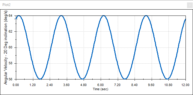
20 deg inclination (left), and 30 deg inclination (right). Look how the angular velocity variation range has increased with the inclination angle.
The most important application of the double Hooke's joint is to avoid the velocity variation.
When the output shaft is 90 deg out of phase with the input shaft (both with same inclinations with respect to the intermediate shaft), the velocity variation is canceled out. In this configuration, the both Hooke's joints acts as a constant velocity joint (CV). Notice that, there is no need for the shaft axes to be on the same plane. however the planes should be positioned with multiples of 90 degrees to each other whilst the input and output shaft axes should have the same inclination with the intermediate shaft. These two videos (right) shows such configurations.
As mentioned earlier, the velocity variation becomes critical only for high speed applications. If you consider the steering column, in most of the cases, they don't have CV property.
When it comes to front wheel drive (FWD) vehicles, the front axle cannot compensate hooke's joints. They use CV joints which are different in design to the Hooke's joint.
The Solidworks model was exported to Matlab Simulink (Simscape) to enable the user to observe the velocity of the output shaft for different combinations of input parameters:
* inclination of the input and output shaft wrt the intermediate shaft
* velocity of the input shaft
The user can easily change these parameters using sliders and observe a real-time plot of the output velocity.
Most importantly, anyone without any knowledge related to Solidworks, Matlab or Simulink can obtain straightforward results using this simple model.
The double Hooke's joint practical setup will be semi-automated to facilitate undergraduate students. Await for more details...
Awaittt...

Comments